Designing an Induction Clutch for Ultra-Low Friction Flywheel Testing
Context
During my master's thesis, I had the opportunity to work within a research group specializing in electric machines and energy storage systems. One of the research topics of my supervisor was the development of ultra-high-performance magnetic bearings for flywheel energy storage systems.
Flywheel storage systems can store energy in the form of rotational kinetic energy. However, one of the main challenges is minimizing energy losses while the flywheel is spinning. To address this challenge, the research team developed an innovative magnetic bearing concept designed to generate extremely low friction torque and therefore reduce the self-discharge rate of the flywheel.
To validate the performance of these bearings, a dedicated test bench had to be developed. Measuring such low friction levels was particularly challenging and became the main focus of my master's thesis.
Goal
The objective of my project was to develop a measurement system capable of accurately quantifying the extremely low friction torque generated by the magnetic bearings.
The chosen measurement principle was based on a spin-down test:
- Place the system inside a vacuum chamber to eliminate aerodynamic losses.
- Accelerate a flywheel mounted on the magnetic bearings.
- Disconnect the driving system.
- Measure the decrease in rotational speed over time.
- Calculate the friction torque from the resulting deceleration.
The main challenge was finding a way to transmit torque to the flywheel during acceleration while ensuring that no parasitic torque was applied during the measurement phase.
What I've Done
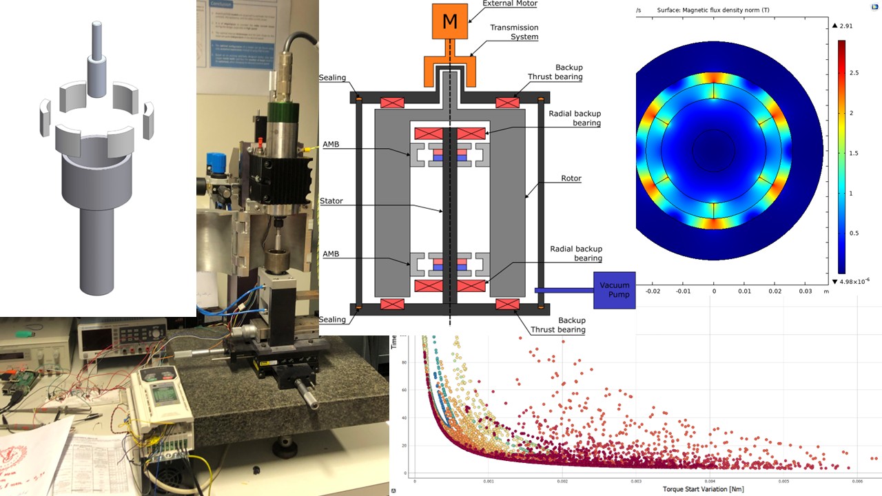
After evaluating several concepts, I concluded that the most suitable solution was to design an induction-based clutchable transmission.
The idea was inspired by the operating principle of an induction motor. Instead of mechanically coupling a motor to the flywheel, torque would be transmitted through a non-contact magnetic coupling.
The system consisted of:
- A rotating conductor located outside the vacuum chamber.
- Permanent magnets attached to the flywheel inside the chamber.
- A thin non-magnetic membrane separating the vacuum environment from the external environment.
When a speed difference existed between the two rotating parts, electromagnetic forces generated torque and accelerated the flywheel.
When the spin-down test had to begin, the speed of the external motor was synchronized with the flywheel speed. Since both parts rotated at the same speed, the slip became zero and the transmitted torque virtually disappeared. This allowed the friction measurements to be performed without introducing significant measurement disturbances.
Electromagnetic Optimization
Once the concept was defined, I optimized the transmission topology using finite element simulations and multi-objective optimization techniques.
The design objectives were:
- Maximize the acceleration torque to reduce testing time.
- Minimize the residual transmitted torque at low slip to reduce measurement errors.
An additional constraint was the presence of the vacuum membrane. The magnetic field needed to cross this membrane while maintaining acceptable mechanical strength against pressure loads.
To find the optimal design, I:
- Built electromagnetic finite element models in COMSOL Multiphysics.
- Developed an optimization workflow using the NSGA-II genetic algorithm.
- Generated Pareto fronts to identify the best compromise between the competing objectives.
The optimization variables included:
- Magnet thickness
- Conductor thickness
- Air gap dimensions
- Back iron geometry
- Various electromagnetic design parameters
Prototype Development
After selecting the optimal topology, I designed and built a complete proof-of-concept prototype.
This involved:
- Designing the mechanical components in SolidWorks.
- Performing structural simulations of the vacuum membrane.
- Comparing simulation results with analytical calculations.
- Manufacturing and assembling the transmission prototype.
- Ordering magnets and mechanical components.
- Building the test bench.
Embedded Control System Development
To control the test bench, I developed a complete embedded measurement and control system.
The system included:
- A Raspberry Pi programmed in Python and C.
- Signal conditioning electronics for the sensors.
- Analog-to-digital conversion circuitry to acquire position measurements.
- Digital-to-analog conversion circuitry to generate motor controller setpoints.
- Motor control algorithms to synchronize the transmission speed with the flywheel speed.
I also developed the software routines required to:
- Automatically perform spin-up and spin-down tests.
- Record measurement data.
- Calculate flywheel deceleration.
- Estimate bearing friction torque.
- Compare experimental results with the finite element predictions.
Results
The project successfully demonstrated the feasibility of the induction clutch concept.
The developed test bench allowed accurate measurement of the extremely small friction torques generated by the magnetic bearings while maintaining minimal interference from the transmission system.
The final measurement uncertainty was approximately 2%, which was considered an excellent result given the very low torque levels involved.
The prototype validated the concept and became the foundation for the next master's thesis project, where the final version of the test bench was further developed.
Tools & Technologies Used
Simulation & Optimization
COMSOL Multiphysics
- Electromagnetic finite element analysis (FEM)
- Torque prediction
- Magnetic field simulations
NSGA-II Genetic Algorithm
- Multi-objective optimization
- Design space exploration
Pareto Front Analysis
- Trade-off analysis between acceleration performance and measurement accuracy
Mechanical Design
SolidWorks
- 3D CAD design
- Engineering drawings
- Structural analysis of the vacuum membrane
Embedded Systems & Programming
- Raspberry Pi
- Python
- C Programming
- Analog-to-Digital Converters (ADC)
- Digital-to-Analog Converters (DAC)
- Sensor signal conditioning circuits
- Motor controller integration
Engineering Domains
- Electromagnetic design
- Electric machines
- Energy storage systems
- Embedded systems
- Control engineering
- Experimental testing
- Data acquisition and analysis
What I've Learned
This project allowed me to combine multiple engineering disciplines within a single system-level project.
I learned how to:
- Design and optimize electromagnetic devices using finite element simulations.
- Apply multi-objective optimization methods and interpret Pareto fronts.
- Develop embedded control systems combining software, electronics and hardware.
- Design mechanical components and validate them through simulation.
- Bridge the gap between theoretical models and real-world experimental results.
- Manage a complete engineering project from concept definition to prototype validation.
Most importantly, I learned how to integrate mechanical, electrical, electronic and software engineering into a functioning experimental system capable of delivering highly accurate measurements.